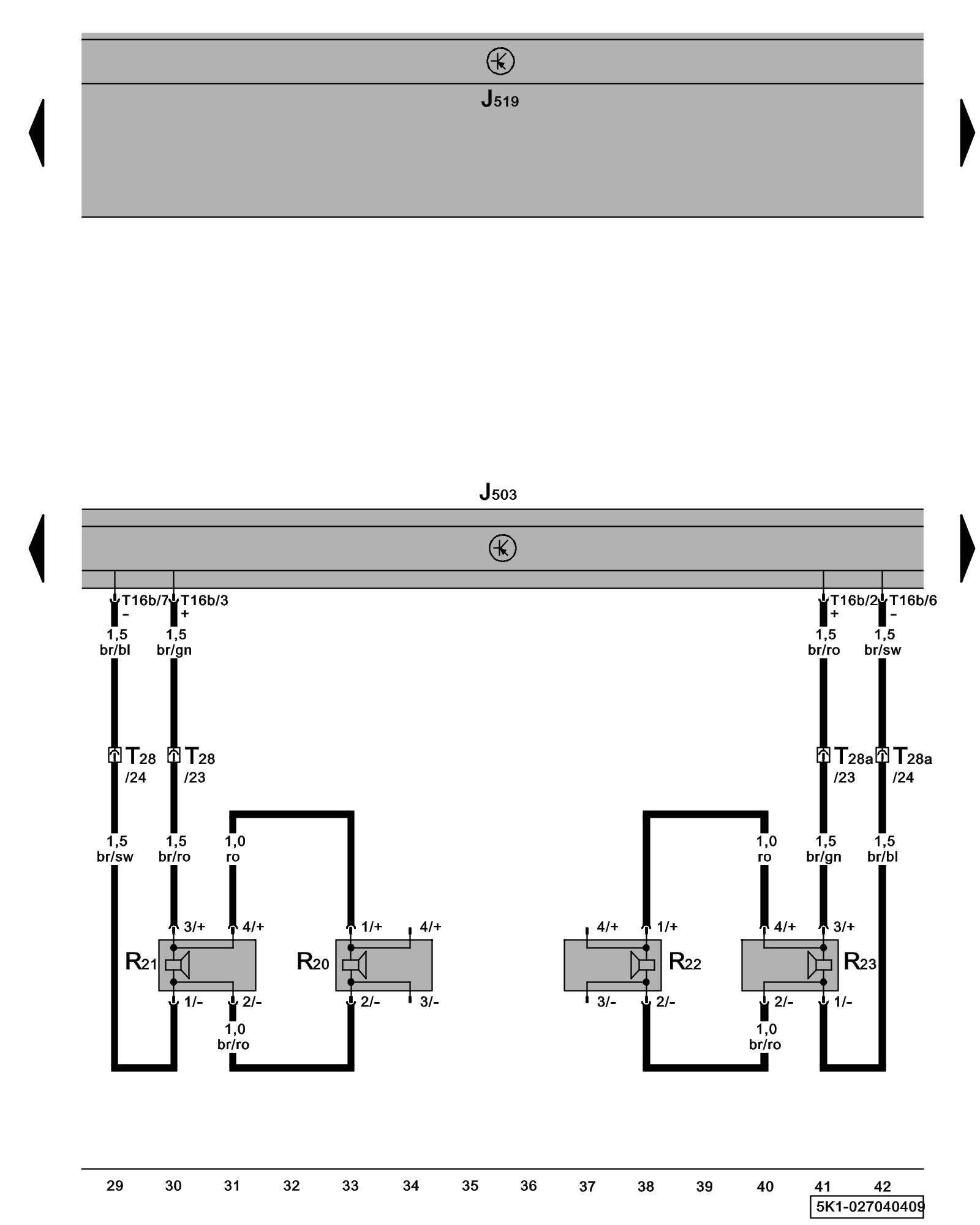
Diagram 27/4 (Tracks 29-42)
IMPORTANT NOTE:
This manufacturer uses "Track" style wiring diagrams.
For information on how to use these diagrams effectively, please refer to Diagram Information and Instructions. Diagram Information and Instructions
Radio/Navigation Display Control Module, Front Speaker
ws = white
sw = black
ro = red
br = brown
gn = green
bl = blue
gr = grey
li = lilac
ge = yellow
or = orange
rs = pink
J503 - Radio/Navigation Display Control Module
Locations
J519 - Vehicle Electrical System Control Module Control modules in front part of vehicle - Overview of Control Modules
R20 - Left Front Treble Speaker
Locations
R21 - Left Front Bass Speaker
Locations
R22 - Right Front Treble Speaker
Locations
R23 - Right Front Bass Speaker
Locations
T16b - 16-Pin Connector
T28 - 28-Pin Connector, connector station A-pillar, left Overview of connector stations and connectors
T28a - 28-Pin Connector, connector station A-pillar, right Overview of connector stations and connectors
Previous Diagram 27/3 (Tracks 15-28)
Next Diagram 27/5 (Tracks 43-56)