Golf/GTI (From 2010) With A Diesel Engine
Transmission, Removing
Special tools, testers and auxiliary items required
• Engine Support Bridge (10-222 A)
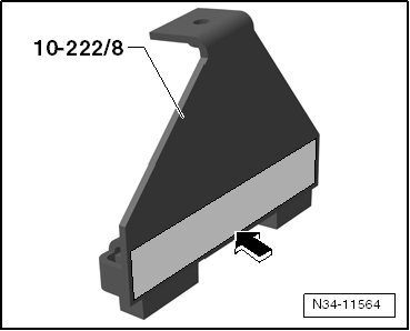
• Engine Support Feet (10-222 A/8)
• Engine Support Adapter (10-222 A/3)
• Adapter (10-222 A/18)
• Transmission Support (3282)
• Pin (3282/29)
• Adjustment Plate (3282/33)
• Transmission Support Jig (3336) (for transporting the transmission)
• Torque Wrench (5-50 Nm) (V.A.G 1331)
• Torque Wrench (40-200 Nm) (V.A.G 1332)
• Engine-/Gearbox Jack (V.A.G 1383 A)
• Bracket (T10346)
• Engine Support Device (3300 A)
• Adapter (VW 771/40) from Slide Hammer-Complete Set (VW 771)
• Hose Clamps up to 25 mm Dia. (3094)
• Grease for Clutch Plate Splines (G 000 100)
• Transmission Support Elements (determine when mounting the adjustment plate on the transmission support)
• M6 x 20 Collar Bolt
• M6 x 80 Collar Bolt
• M10 x 20 Bolt
The engine support bridge (10-222 A) and the engine support feet (10-222 A/8) will be mounted on the longitudinal members later in the procedure.
• To protect the edges of the fenders, cover both engine support feet (10-222 A/8) with cloth tape - arrow -. Refer to the Parts Catalog.
- Obtain the anti-theft code, if a coded radio is installed.
- Turn off the ignition and disconnect the battery ground cable.
Later in the procedure, the engine support bridge (10-222 A) is connected to the engine lifting eyes.
- Remove the engine cover if it is blocking the lifting eyes.
- Remove the air filter housing if it is located near the battery.
- Remove the battery and the battery tray.
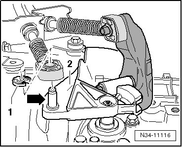
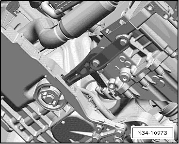
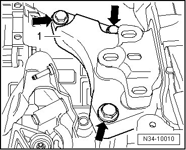
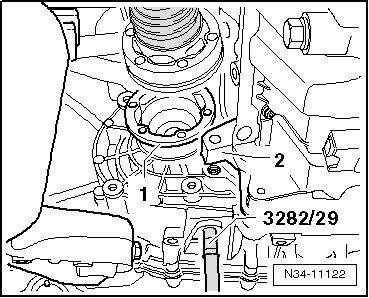
- Remove the shift cable lock washer - 1 - from the transmission shift lever - 2 - and remove the cable from the pin - arrow -.
- Remove the cable retainer from the selector cable.
• To avoid damage to the selector cable, the cable retainer must be disconnected from the selector lever before removal.
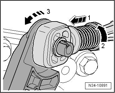
- Pull the locking mechanism all the way forward in the - direction of arrow 1 - and then unlock it to the left in the - direction of arrow 2 -.
- Press the relay lever forward, in the - direction of arrow 3 -.
- The relay lever is removed together with the cable retainer later in the procedure.
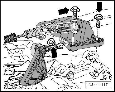
- Remove the cable bracket bolts/nut - arrows - from the transmission, move it to the side and secure it.
with a Pipe between the Clutch Master and Slave Cylinders
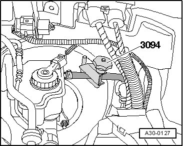
- Clamp off the supply hose to the master cylinder using a hose clamp up to 25 mm dia. (3094).
with a Hose/Line Assembly between the Clutch Master and Slave Cylinders
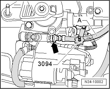
- Clamp off the hose on the hose/line assembly - A - to the clutch slave cylinder using a hose clamp up to 25 mm dia. (3094).
Continuation for All
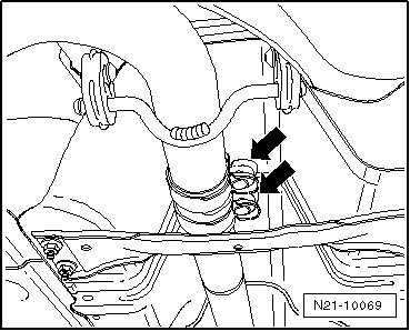
- Pull the clip - arrow - for the hose/line assembly or pipe out to the stop.
- Remove the hose/line assembly or pipe from the breather assembly/slave cylinder and seal it off.
Do not press the clutch pedal anymore.
- Remove the ground strap - 1 - from the top starter bolt.
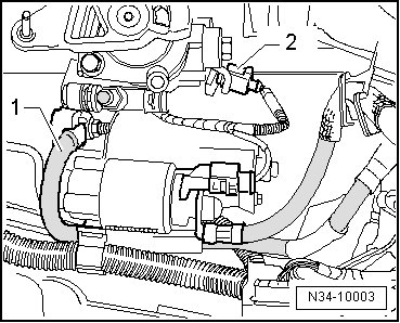
- Disconnect the connector - 2 - from the backup lamp switch.
- Disconnect the connector and the wire from the starter.
- Remove the upper engine to transmission bolts - arrows -.
- Remove the upper bolt from the starter.
- Install the bracket (T10346) in the rear most hole out of the three holes for the battery tray.
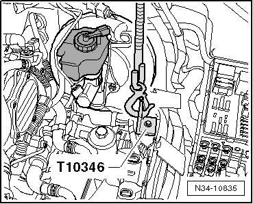
- Use a M6 x 80 collar bolt or one of the battery tray bolts for this.
- Disconnect any hoses and wires in the area of the lifting eyes on the engine.
- Install the engine support bridge (10-222 A) in front of the engine hood support.
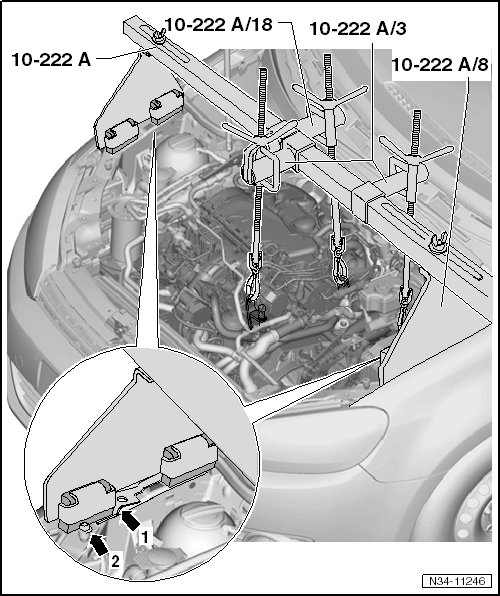
- Use the following special tools:
• Engine support adapter (10-222 A/3)
• Engine support feet (10-222 A/8)
• Adapter (10-222 A/18)
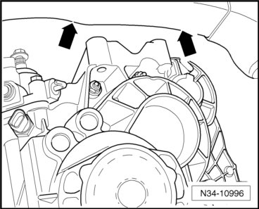
- Position the engine support feet (10-222 A /8) :
• On the upper longitudinal members, directly in front of the ridge (- arrow 1 -) next to the bolt (- arrow 2 -)
- Then, attach the bracket (T10346) to the engine support bridge spindle.
- Hook the other spindle to the left lifting eye on the engine.
- Pretension the engine and transmission assembly and engine support bridge via the spindles.
The left drive axle bolt - arrow - must be removed later in the procedure.
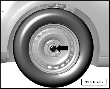
- With the vehicle still sitting on its wheels, loosen the left front drive axle bolt - arrow - a maximum of 90°. Otherwise the wheel bearing will get damaged.
- Remove the noise insulation.
- Remove the lower part of the left front wheel housing liner..
- Remove the left front level control system sensor from the control arm, if equipped.
- Remove the bracket from the starter.
- Remove the starter.
- Release the clamps - arrows 1 and 2 - and remove the charge air hose.
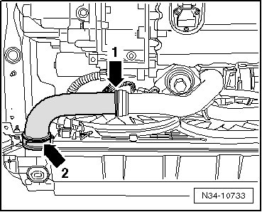
- Remove the charge air pipe from the engine.
- Remove the right charge air hose from the charge air cooler.
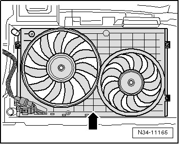
- Remove the fan shroud - arrow - and fans.
- Remove the exhaust system suspended mount bolts - arrows - from the subframe.
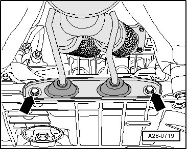
- Disconnect the exhaust system at the double clamp - arrows -.
- Tie up the front exhaust pipe or lay it on the tunnel brace.
- Remove the pendulum support.
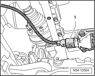
- Disconnect the connector - 1 - from the oil level thermal sensor.
- Remove the left coupling rod from the stabilizer bar and move it to the side.
- Remove the left drive axle.
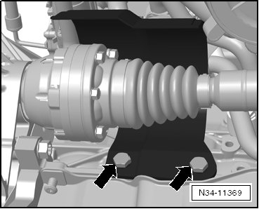
- Remove the right drive axle heat shield bolts - arrows - and shield, if equipped.
- Remove the right drive axle from the transmission and tie it up.
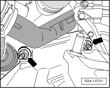
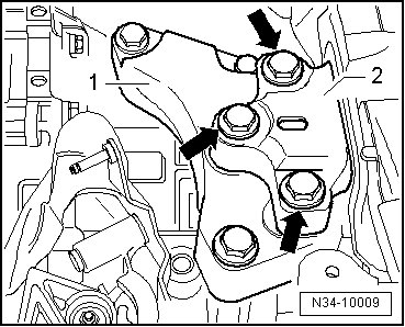
- Remove the transmission mount bolts - arrows - securing the transmission mount - 2 - to the transmission mount bracket - 1 -.
- Lower the transmission by adjusting the spindles, which are attached to the engine, approximately 40 mm - a -.
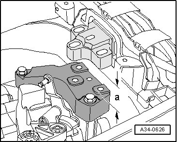
• When lowering the engine and transmission assembly, pay attention to the wires, hoses and radiator.
- Remove the transmission mount bracket - 1 - to transmission bolts - arrows -.
- Remove the relay lever with the cable retainer. Refer to => [ Plastic Relay Lever ] Plastic Relay Lever.
- Remove the transmission shift lever from the gear shift shaft.
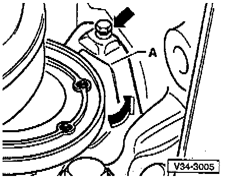
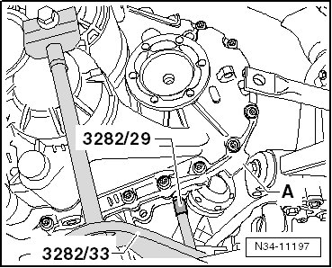
- Remove the small flywheel cover plate bolt - arrow - and plate - A -, if equipped.
- Remove the lower engine to transmission bolt - 1 -.
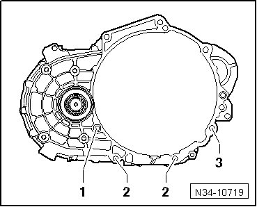
• Loosen the engine to transmission bolt - 3 - and leave it in hand tight.
- Install the bracket (T10346) with the bolt - 1 - in the left threaded hole in the subframe.
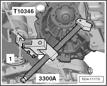
Bolt - 1 - = M6 x 20 collar bolt
- Install the engine support device (3300 A) to the bracket (T10346).
- Place a cloth between the engine support device (3300 A) and the oil pan.
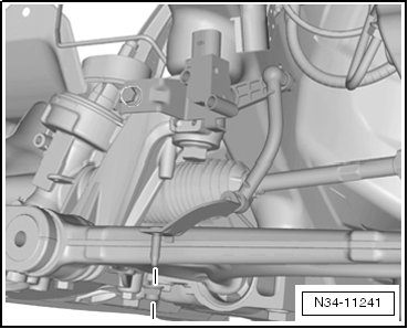
- Push the engine forward using the spindle on the engine support device (3300 A). Note the following when doing this:
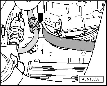
• The Air Conditioning (A/C) compressor - 2 - must not touch the refrigerant line - 1 - - arrow -.
• The generator must not touch the refrigerant line.
• The pressure pipe must not touch the radiator.
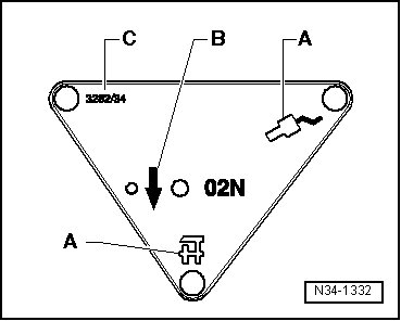
To remove the transmission, the adjustment plate (3282/33) must be installed on the transmission support (3282).
- Install the transmission support (3282) to the engine-/gearbox jack (V.A.G 1383 A).
- Align the arms of the transmission support so that they match up with the holes in the adjustment plate.
- Install the support elements - A - as illustrated on the adjustment plate.
- Install the pins (3282/29) in place on the adjustment plate - C -.
- Position the engine-/gearbox jack (V.A.G 1383 A) under the vehicle. The arrow symbol - B - on the adjustment plate points in the direction of travel.
- Align the adjustment plate so that it is parallel to the transmission.
- Install the adapter (VW 771/40) into the threaded hole in the transmission as illustrated.
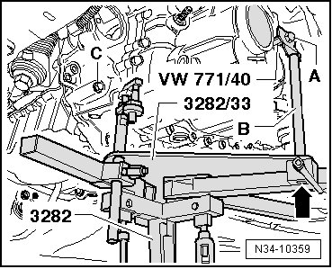
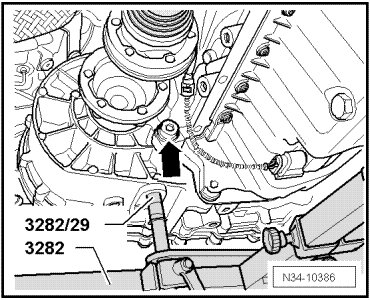
- Install the pin (3282/29) into the hole on the transmission for the pendulum support bolt.
- Secure the transmission to the transmission support (3282) using a bolt (MD) - A -.
The arm - B - must be flush with the guide on the transmission support (3282) - arrow -.
Remove the engine to transmission bolt - arrow -.
- Remove the engine to transmission bolt (- item C - in the previous figure) and then the lower engine to transmission bolts.
- Separate the transmission from the engine (alignment sleeves).
- Move the transmission in the area of the differential with the spindles on the transmission support (3282) into an angled position.
• The differential must face upward.
The right flange shaft - 1 - must be guided over the cylinder block bolt flange - 2 -.
- Guide the transmission and the differential over the subframe - A - and swing it out.
- Pay attention to the longitudinal member - arrows -. Then carefully lower the transmission.
• Pay attention to the lines when lowering the transmission.