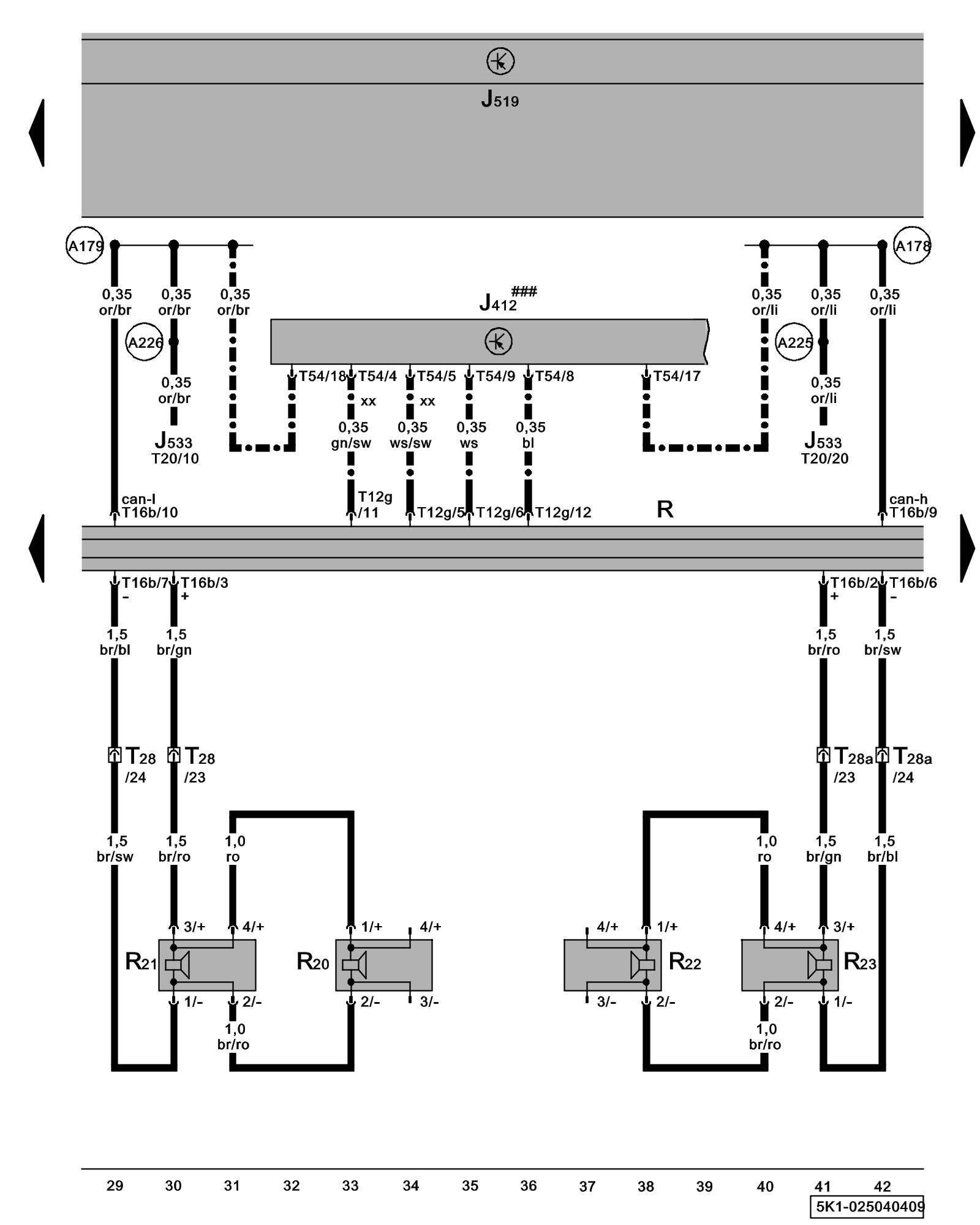
Diagram 25/4 (Tracks 29-42)
IMPORTANT NOTE:
This manufacturer uses "Track" style wiring diagrams.
For information on how to use these diagrams effectively, please refer to Diagram Information and Instructions. Diagram Information and Instructions
Radio, Front Speaker, Operating Electronics and Telephone Control Module
ws = white
sw = black
ro = red
br = brown
gn = green
bl = blue
gr = grey
li = lilac
ge = yellow
or = orange
rs = pink
J412 - Operating Electronics and Telephone Control Module Control Modules in The Rear Of The Vehicle
J519 - Vehicle Electrical System Control Module Control modules in front part of vehicle - Overview of Control Modules
J533 - Data Bus On Board Diagnostic Interface Control modules in front part of vehicle - Overview of Control Modules
R - Radio
Locations
R20 - Left Front Treble Speaker
Locations
R21 - Left Front Bass Speaker
Locations
R22 - Right Front Treble Speaker
Locations
R23 - Right Front Bass Speaker
Locations
T12g - 12-Pin Connector
T16b - 16-Pin Connector
T20 - 20-Pin Connector
T28 - 28-Pin Connector, connector station A-pillar, left Overview of connector stations and connectors
T28a - 28-Pin Connector, connector station A-pillar, right Overview of connector stations and connectors
T54 - 54-Pin Connector
(A178) - Infotainment High-Bus Connection (in instrument panel wiring harness)
(A179) - Infotainment Low-bus Connection (in instrument panel wiring harness)
(A225) - Infotainment High-Bus Connection 2 (in instrument panel wiring harness)
(A226) - Infotainment Low-bus Connection 2 (in instrument panel wiring harness)
### - Components not available on system preparation
-^- - Only models with telephone/ telephone preparation
xx - Only Universal Cellular Telephone Preparation (UHV) Low
Previous Diagram 25/3 (Tracks 15-28)
Next Diagram 25/5 (Tracks 43-56)